COMP 150 Gates Homework
Assignment Index
Course
Home Page
This is an individual
assignment, not a pair
assignment.
You may write it on paper and scan it before uploading into
Blackboard.
- (5 points) Create circuit diagram for the Boolean
expression (AB + C)D.
- (5 points) Write a Boolean expression for the output of this
circuit:
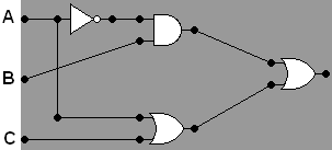
Remember wires only connect at dots.
- (5 points) Write a Truth Table for the Boolean expression
(A+B')C.
Include columns for the inputs A, B, and C. Please include
a column
in your truth table for the output of each intermediate expression.
Include rows for all 8 combinations of input variables.
- (5 points) A three-way majority circuit is one
with three inputs and a
single output which is set to 1 whenever two or more of the
inputs (the majority) are set to 1. There are eight
possible combinations for the input settings.
Please give a truth table which lists rows for all eight input
combinations along with
the output setting for each case.
- (5 points) Write a Boolean expression for the output of the
three-way majority circuit from problem 4.
- (5 points) Construct a circuit which implements the
three-way majority function
discussed in the previous two questions. You may use AND and OR
gates with more than 2 inputs to make it easier.
Submit in Blackboard. (Include the extra credit portion
below if
you like.) You have presumably drawn some pictures. If they
are on paper, scan your work into a computer computer file. You
will need to submit a modified log.txt (no reference to a partner).
Extra Credit A. (5 points)
Interestingly, any given boolean function can be calculated by a
circuit consisting solely of NAND gates.
Extra Credit B. (5 points)

Consider the component with the M2 symbol at the left, above. M2 is the symbol I give for a multiplexer with two
control lines, on the bottom, least
significant bit to the left, and
with four data input lines, on the left, with lines for data bits 0-3 going
down from the top, and the single output line on the far right.
Complete the circuit diagram started below, to
create an M4 multiplexer circuit. At this point all that is shown are the four control lines, at the
bottom, least significant bit
at the left, and 16 data input
lines on the left with lines for data bits 0-15 going down from the top,
and one output line at the far right. Draw in five of these M2
multiplexers, lots of wires, and no other gates,
to correctly connect these inputs and output. Be sure to draw a
clear dot where you mean two wires to connect. (Hint: look at the
relationship between the
circuit diagrams in the notes for the multiplexer with one control line
and the multiplexer with two control
lines.)

Assignment Index
Course
Home Page